I needed a beam antenna for 2m and another for 70cm. What would they be? Yes, I too have bashed up the odd aluminium antenna with varying degrees of success in engineering and construction excellence and performance with elements slightly askew, etc.
Some time ago, I was introduced to the DK7ZB antenna matching system and Martin's web site, saw the range of antenna designs and thought, yes, I'll have to make one. They seemed simple enough to build but, wait, they require insulated element brackets. Sure, they are available but at a price. Is there some way I could make my own mounts with repeatability?
I decided that the most readily available insulating medium might be something that almost every household has - a kitchen cutting board. We had one that was about a centimetre thick. Should be just right. Anyway, when I went looking, I couldn't find any that thick. Although I considered gluing two thinner boards back to back, I decided to have a go with a single thickness as it seemed thick enough. $AUD4.00 bought me a polyethylene cutting board that would give me all the insulators required for a single antenna. They may not last forever in the Australian sun but for less than 40c per insulator, I'm not going to complain.
I should say here that I do not know the exact RF performance specifications of polyethylene but I've used it anyway.
I chose a 9 element design for 2m and a 12 element design for 70cm. I didn't go any bigger to limit the wind loading at the top of the tower. I suggest you refer to the DK7ZB site for specifications for boom length, element lengths and spacings, etc.
I dismantled a couple of television antennas to get a 25mm booms and 12mm and 8mm elements. Cost? Nothing except picking them up from VK3JGL. Thanks Graham.
Construction details are the same for both antennas although the description is written for the 70cm one.
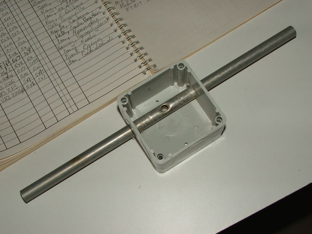
 The Radiator Mounting Box - The radiator in this design is 12mm while the other elements are 8mm. The first task was to set the radiator in its mounting box to see what its height above the boom would be. This would decide the height of other elements above the boom as they need to be in the same plane.
I used a plastic box about 70mm x 70mm inside dimensions. Close fit element holes were drilled through from one side to through the other. I initially mounted the radiator in one piece, planning to split it once the construction neared completion.
 The Insulators - The cutting board that I used was approximately 327mm x 217mm and provided 12 insulators at approximately 117mm x 42mm. I say approximately as the saw cut modified the dimensions slightly. As a means of working out the insulator size, I placed the radiator box on top of the boom and measured the centre of the radiator from the top of the boom. All elements mounted on insulators are screwed to the top (or bottom) edge of the insulators so that their centres are the same height above the boom as the radiator centre. The insulators each have a snug fit hole for sliding on to the boom. There needs to be sufficient clearance on one side of the hole to permit boom to element clearance and on the other side for a fixing screw into the boom.
For the record, my dimensions allowed for 9mm on one side and 10mm on the other side of the 25mm boom hole.
No attempt has been made to make the insulators look pretty. It is an antenna, not an aesthetic conversation piece. If you use this idea and want yours to look better, feel free to change them and be prepared to spend the time doing it.

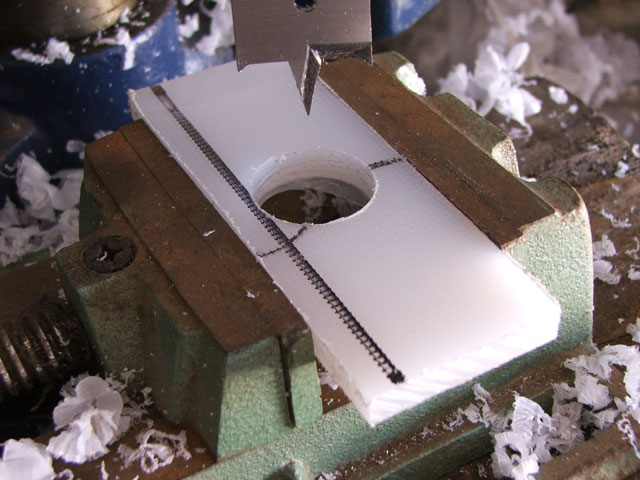
 Drilling the Boom Hole - I cut a drilling centre template from scrap circuit board, placed it on each insulator and drilled a pilot hole. Polyethylene is quite easy to work. I simply clamped the material horizontally in a pedestal drill vise and drilled it with a spade bit at a slow speed and gradual pressure to avoid overheating and distortion. The requirement was to drill a close fittimg perpendicular hole so that the elements would be securely located. The insulators ended up being a very firm fit on the boom.
Incidently, if using a square boom, you don't need to slide the insulators on to the boom. Just screw a suitable piece of cutting board flat to the upper or lower face of the boom and then screw the elements to it.
 Element Fitting - I left the radiator until last. Once the insulators were ready, I centrally located each element on the appropriate insulator edge and screwed them to the insulators, taking care that everything was exactly positioned. It is easier to keep everything square in a pedestal drill than it is with a hand power drill. The screws I used were a little too long but they were all that I had.
When the elements and insulators were slid into the measured position on the boom, I turned the boom upside down so that the elements rested on the floor. Standing on the boom between each element forced the elements to align in the same plane. Easy. They were then secured in position with a single screw into the boom from the non-element edge. A nice, neat, perfect job.
Radiator Fitting - The radiator will be fitted in the next few days. It needs a little more attention when screwing the mounting box to the boom. I will probably use saddle clamps around the boom to permit a small degree of alignment after screws through the bottom of the box were a little imprecise.
Details of the coax transformer are available from the DK7ZB web site.
Summary - So, there you have it. Simple construction and cheap insulator mounts. The construction is taking place in January, 2005. The useable life of the insulators is still to be determined. If they don't measure up, I will try and locate a substitute. Details will be posted here if necessary.


 The Radiator Mounting Box - The radiator in this design is 12mm while the other elements are 8mm. The first task was to set the radiator in its mounting box to see what its height above the boom would be. This would decide the height of other elements above the boom as they need to be in the same plane.
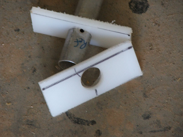 The Insulators - The cutting board that I used was approximately 327mm x 217mm and provided 12 insulators at approximately 117mm x 42mm. I say approximately as the saw cut modified the dimensions slightly. As a means of working out the insulator size, I placed the radiator box on top of the boom and measured the centre of the radiator from the top of the boom. All elements mounted on insulators are screwed to the top (or bottom) edge of the insulators so that their centres are the same height above the boom as the radiator centre. The insulators each have a snug fit hole for sliding on to the boom. There needs to be sufficient clearance on one side of the hole to permit boom to element clearance and on the other side for a fixing screw into the boom.
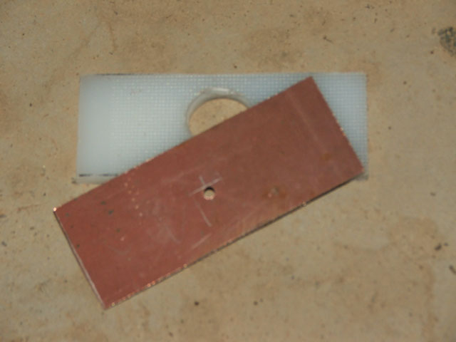
 Drilling the Boom Hole - I cut a drilling centre template from scrap circuit board, placed it on each insulator and drilled a pilot hole. Polyethylene is quite easy to work. I simply clamped the material horizontally in a pedestal drill vise and drilled it with a spade bit at a slow speed and gradual pressure to avoid overheating and distortion. The requirement was to drill a close fittimg perpendicular hole so that the elements would be securely located. The insulators ended up being a very firm fit on the boom.
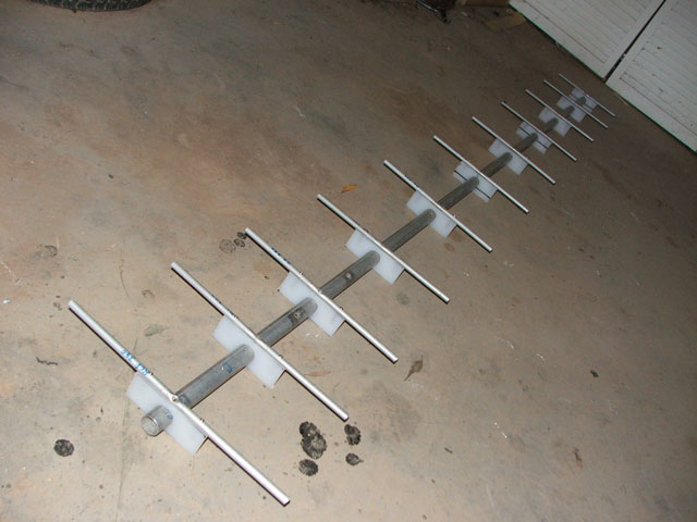 Element Fitting - I left the radiator until last. Once the insulators were ready, I centrally located each element on the appropriate insulator edge and screwed them to the insulators, taking care that everything was exactly positioned. It is easier to keep everything square in a pedestal drill than it is with a hand power drill. The screws I used were a little too long but they were all that I had.