A caravan?
In about 2006, I put forward a suggestion that the Midland Amateur Radio Club consider the purchase or construction of a caravan to facilitate creating a higher public profile for local amateur radio. The caravan was to house operating equipment, brochures and other advertising paraphernalia and anything else that it considered would enable easy setup and operating at virtually a moment's notice almost anywhere. Sometimes things happen very slowly and after a period of little activity, I decided to pursue the idea at a more private level. Many, many changes have been made since.
The original caravan suggestion was eventually discarded for reasons related to where it would ordinarily be housed and who would be able to provide a suitable vehicle to tow it at any given time. In looking for a suitable alternative, I considered a number of essential requirements that covered and even expanded the required functionality. If a caravan was not used, what else could be provided for quick setup and operating convenience. Could a trailer, even purpose-designed, fill the bill? Could a telescopic mast be incorporated in it? If a trailer was a possibility, what about weather protection for the operators?
A trip with a general concept to a local, advertised as 'we build to your requirements' trailer manufacturer, resulted in a 'not interested' response. I was told it was not in their normal line of business and that it is difficult to weld steel sheets without ending up with heat expansion ripples. I won't be buying any trailers from there at any time.
A bit of Internet research came up with quite a few variations of communications trailers but they were all either too ambitious or too expensive. However, a couple of useful ideas came out of it.
If a trailer could be constructed to provide the operating requirements such as telescopic tower, generator and various storage facilities, the covered public area could be provided by something similar to an add-on tent fixed to the side. Sounds like it might just be possible and the tent idea was relegated to the background as concentration was applied to a suitable trailer and telescopic mast.
Monica, VK3FMON, and I attended joint campouts at the Whipstick Environment Centre and Ballendalla, Victoria with Bendigo District Astronomical Society in 2009. Although both weekends were very enjoyable, the amateur radio related difficulties and inconveniences of attending such events were discussed on the way home. The same 'problems' are associated with Club events - unhooking all the transmitting gear, loading it into the vehicle along with camping gear, driving to the event, unloading all the gear and setting it up, erecting antennas on whatever supports can be found, sleeping on concrete, etc. After the event the process is reversed. A lot of work for a campout. Not dissimilar to field days and other public events, is it?
The Vehicle
 Maybe we could purchase a vehicle (van?) that we could sleep in and set up the operating gear? And if we could come up with a small, skeletal, trailer mast, wouldn't that satisfy the antenna mounting requirement? Travel to the site, extend the mast, hook up and you are away. It just might be possible.
OK, so now we set out on a quest to find a suitable second hand van. Everything we looked at was discarded. After all, a van is just a van and a little pedestrian. Our wanderings eventually led us to the purchase of a 2006 Mazda MPV - a 3 litre, seven seater with seats designed for removal, only 50,000 kilometres on the clock and all the creature comforts of a conventional vehicle. Removing the two most rearward seats makes a station wagon and removing the centre row as well makes a panel van. Seat removal/refitting only takes moments. Now I know why there are so many of this type of vehicle on the roads. We can have a vehicle that is easily configured to suit the occasion and those seats have since been in and out many times.
We attended another joint campout in 2010. This time, we slept in the vehicle (big comfort improvement) but had to put a lot of the stuff we had to take with us outside, underneath. Once again, operating convenience came under discussion. Time to finally do something about it.
My own design.
So, now I start coming up with my own communications trailer. Let's do it, prove the concept and the Club can consider modifications for its own purposes if needed.
My initial thoughts were for a purpose-designed trailer with the idea of taking it to an alternative trailer manufacturer for construction. Various methods of locking the mast in the vertical position and various other matters were designed. I also considered air operated masts but rejected these due to cost. Telescoping steel pipe was also considered for a short time but was rejected in favour of the more typical triangular, steel lattice type. It became obvious that overall costs could very readily escalate to the too-high bracket. Maybe a commercially manufactured trailer could be used instead - with a triangular, steel mast.
This latest change led to Monica suggesting that a common tradesman's trailer might be pressed into service. A trip to a different local manufacturer indicated possibilities. The concept could be applied with modification to accommodate the mast up the centre. Stability requirements necessitated the mast, when extended, would be positioned in the centre of the trailer. A storage bin on each side of the trailer would suit the storage requirements. Yes, it just might work.
Serious consideration of the tradesman's trailer concept led to thinking about a conventional trailer with reinforced floor centre and custom made storage bins. The trailer manufacturer said, 'Draw it up and we'll see what we can do.' This approach was also looking as though it might be costly.
The whole unit would consist of a few basic modules - the trailer, the mast, supporting framework, storage bins and stabilising or levelling outriggers. The design concept was for a two section, triangular, tilt-over mast with supporting framework that could be removed from the trailer if ever there became a need for conventional trailer functionality. There would also be at least two storage bins - one of which could be the basis of an operating console. Mast deployment would be via a small winch with various automatic locking fittings included. Emphasis was to be placed on operator comfort, convenience and flexibility.
The Trailer
 Suddenly, the opportunity of purchasing a second-hand trailer, made by this recent manufacturer, came up. We arranged to take the trailer for a test drive (?) and decided it had possibilities. It was an 8' x 5' tandem with rocker springs. The carrying capacity would be more than ample and I had more than 500kg to play with before I exceeded the somewhat low 960kg towing capacity of the vehicle. Maybe I could make the mast and the local manufacturer could provide the storage bins, etc. On discussing this with the local manufacturer, we found out that they didn't actually locally manufacture at all.
Where do we go from here? Could I really do it all myself?
Further consideration led to the possibility of making the mast and all other items demountable so that the trailer could be used for conventional purposes if required. A handy feature if at all possible. I decided to explore this possibility. Could I build it to satisfy my requirements and still contain costs to a reasonable level?
All this meandering and design changing was starting to become a little wearing. Many hours had been put into all the designing and planning. It was time to prove the concept or close the books. Enough of exploring possibilities. Let's get down to business and make a communications trailer.
Getting Ready
I decided to base the mast design on my own tilt-over mast that I normally use at home. As the trailer mast wouldn't be as high or have to carry such a load, if it is made of similar material it should be more than strong enough. Using the equation ((2 x overall trailer length) minus 1m overlap) plus trailer floor height) gave an actual extended mast height in excess of 7 metres with the purchased trailer.
The basic concept was now worked out and trailer loading information was downloaded from the VicRoads web site - just to make sure that what I was doing was going to be legal. The closest diagram to my requirements showed a standard, single axle box trailer with no portion of the load being able to extend beyond the tray area and not suitable for my purpose. A further search for more information that I could use came up with yacht trailers. These permit a considerable overhang to the rear, bow overhang to near to the tow hitch and even mast extension over the towing vehicle - to a point. Where were the instructions for radio masts? I needed to know because my concept was depending on this.
VicRoads soon cleared up any uncertainty. Yes, I was allowed to extend my mast forward to above the tow ball - provided it was up the centre of the trailer and not on one side. This is to avoid the possibility of turning a corner and have the mast go one side of a light pole and the tow vehicle, the other. Perfect! Come to think of it, side mounting would certainly restrict turning one way at least.
A trip to a local steel merchant after calculating the approximate steel requirements and the parting with a number of dollars saw a package of steel heading home.
As this was going to be a major construction project I also purchased a steel cut-off saw. I managed to borrow one of those clever automatic darkening welding helmets as well. Amateurs are considerate and helpful to their fellow amateurs aren't they?
Making the Mast
 My forty years welding experience runs to constructing a small boat trailer - that was how I came to have a welder in the first place - a wood fire box, the band trailer for the now-defunct Bendigo band The Renegades, and various odds and ends. Welding is a practiced art and practice opportunities over forty years or so were few and far between. I decided I had better do a bit of Internet research for some pointers. I found a couple of short videos that answered a few queries that I had. I had also managed to overhear a conversation about getting a good brand of welding rods.
So, armed with this new-found knowledge and a good brand of welding rods, I was now confident that I could satisfactorily complete the project.
Each of the two mast sections consist of three vertical steel tubes and a combination of horizontal and angled steel rod braces. The first construction task was the inner/upper mast section. The size of this section would then dictate the size of the outer/lower section. A small triangular template was fabricated to ensure that the construction was neat, uniform and professional or, as much as it could be. The template would be used to accurately fix the separation distance between the three vertical tubes and the accurate placement of the horizontal bracing. The template was moved along the length of the section as each level of horizontal bracing was added. Steel rod was then bent to form three angular braces between each horizontal one. Nothing difficult so far.
 The template worked a treat, making the section construction quite fast and easy. The first day saw the completion of the upper mast section to the point where it was set aside for final weld checking and finishing.
The next day, a second triangular template was made for the larger outer/bottom mast section. The construction principle was much the same as the previous section but with more frequent horizontal bracing with a singular angle brace between. No bending for these angle braces, They were all individually cut.
 The third day saw the completion of this mast section to the same level as the other. The two sections fit together and telescope very nicely. Progress is going very well and the finished job is satisfyingly more professional looking than my own mast. I wonder if it was made in someone's back yard. It wasn't bought commercially.
Mast Section-to-section Clearance
 The outer mast section was sized to easily fit around the inner section. Post-construction is not the time to find out that the sections do not have enough clearance. Although there is far less slack then there is with my own fixed mast at home, there is still a certain amount of slack between the sections. The higher the inner mast is extended, the more this shows up.
A number of chain link off-cuts welded to the vertical tubes has improved this immensely. Initially, the mast sections snagged on a couple of mast braces welds. A small amount of filing excess weld soon fixed that and the mast slides in and out beautifully - with minimal friction.
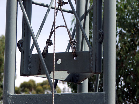
T cable is tied-off at the bottom of the inner mast as pictured. The two connections were required to ensure that the raising force was more-or-less equally applied to the mast section to ease progress and to also ensure proper operation of the vertical lock.
Mast Support
 The next task was to construct the supporting framework to be mounted in the trailer. This basically consisted of a central supporting section with angled braces foreword, rearward and to both sides. It also contains the hinge on which the mast rotates between the horizontal and vertical planes and the winch used to make it all happen. I spent a couple of days constructing this as there were a few steel items, angles and much trial and error getting it all to fit properly. Actually, the second day on this task saw some of the first day's work demolished for a better, faster and easier design. Construction was interrupted by a trip to town for some more steel, a large drill bit, a winch and some sundries.
 The framework was then fitted temporarily in the trailer firmly secured with five bolts through the floor for strength and ease of removal if and when required.
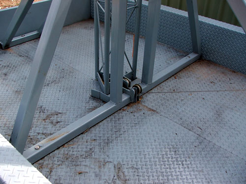 This is an image of the rear half of the mast support.
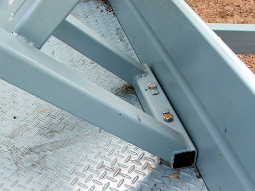
Mast Hinge
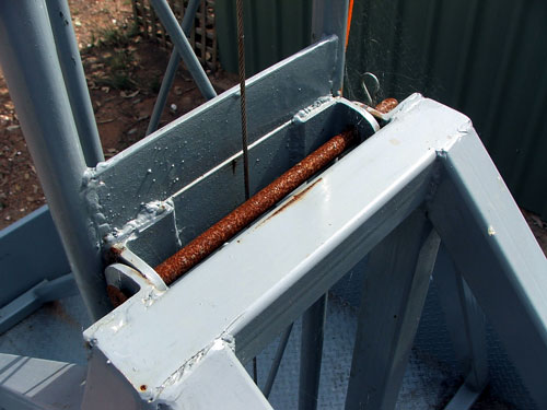 The mast hinge was initially mounted on top of the mast support but it became obvious that there was insufficient cable clearance between the mast and the bracket in the transport position and this would result in accelerated cable wear. The hinge was removed and shifted to the rear of the mast support.
The mast hinge bolt is shown rusted here as it would not have fitted if I had painted it. Gives a nice contrast in the picture don't you think?
Vertical Mast Lock
 This lock is designed to hold the mast in the vertical position. Its operation is automatic and the lock lowers and secures itself against the mast support as soon as the inner mast section has been raised by about 50mm or so. It releases when the inner section has completely lowered.
I thought I had it all covered but, they wanted to, someone could easily release the vertically lock and, with the winch in the released brake position, allow the mast to quickly assume the horizontal attitude - fully extended. Not the safest of situations. I will consider fitting a lug with a padlock to remove any possibility of it happening.
The Winch
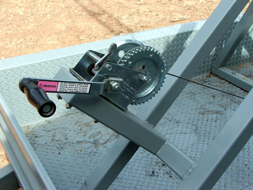 Locating the winch bracket presented a headache or two. This problem is that I am thinking I might mount another storage bin at the front left down the track. I also want to keep the area immediately in front of the load area clear in case it is also required later. The final position is not entirely ideal but acceptable. The winch itself is mounted slightly off-centre to clear any front bin that may be installed. The winch cable is stainless steel to avoid the affects of rust.
Guide Foot
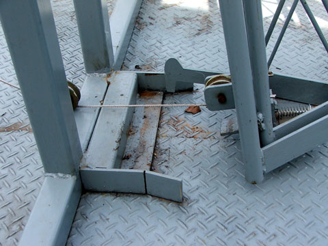 The guide foot was made to guide the bottom of the mast into position as it reaches the vertical position. It also provides lateral support and takes the strain off the hinge pin.
Anti-Extension Lock
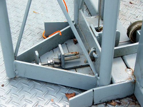 The anti-extension lock prevents the inner mast section extending until the mast has obtained the vertical position. It is showed her in the retracted position. There is a tongue that is forced against the tension spring by the mast mount, thereby withdrawing a pin that goes through both mast sections.
It is most important to ensure that this lock operates, otherwise the inner mast section could project forward during transport or during raising if the extension force is less than the raising-to-vertical force. The cable tension will tend to extend the inner mast section whenever the mast is below about 45 degrees.
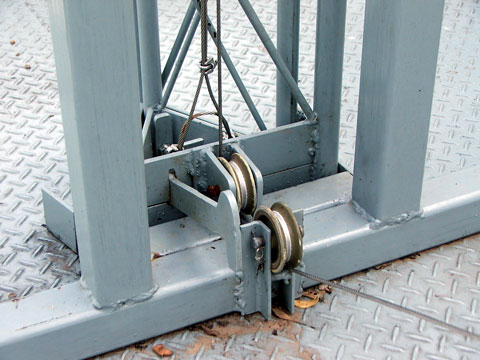
Mast Pulley
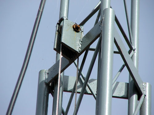 A pulley is attached top of the outer mast section. The cable runs from the winch, through a pulley at the bottom, on the mast support, through another pulley at the bottom of the lower mast section, up to the top of the lower mast section, over this pulley and down inside, between both mast sections to the bottom of the upper mast section. A cable clamp will be fitted to prevent the inner mast being raised beyond a 1 metre overlap.
The mast extension has now passed its first test - not with the intended stainless steel cable but with poly rope.
Extension Lock
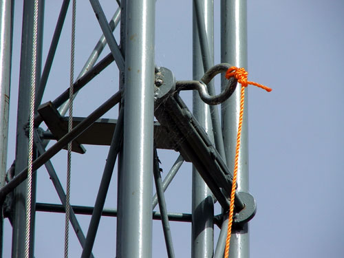 This lock is probably the least attractive part of the whole project - despite the fact that it does exactly what it is supposed to do. As the winch operator stands at the front of the trailer, the lock was initially attached to the forward-facing face of the mast. This position seemed logical and appropriate but it could only be operated with the mast fully extended due to fouling the winch cable. Placing it on one of the side faces allowed operation at 1 metre height increments.
However, the lock had to be butchered a little to clear the angled mast bracing. It will be modified when the urge to pretty it up outweighs the urge to leave it as it is.
It is a simple matter to operate. The mast is raised a short distance past the desired height and a pull on the cord flips the lock into or out of place.
Stabilisers and Levellers
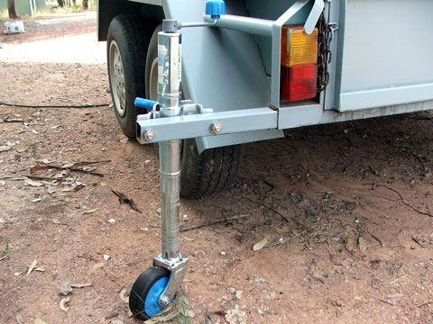 The easiest and cheapest method of providing stabilising outriggers is to use modified trailer jockey wheels for the adjustable jacks and four of these were purchased from a local auto parts supermarket for around $30.00 each - including mounting brackets. They were on sale at exactly the right time. As it turned out, the trailer is far, far more stable than it was thought it would be but they are required at least for levelling purposes.
The inherent stability of the trailer resulted in only three jockey wheels being used - the one at the front and two that slide into square tubing at the rear. They still need to be modified by replacing the wheel with a metal plate.
Front Support
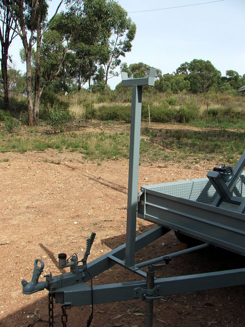 The front support is a simple affair. Its purpose is only to provide a resting place for the mast in the transport position.
Sometime in the future I will fit a lockable clamp to hold the mast in place for transport.
Completion and Use
 The fully extended height of the mast itself above ground is 7.54m - a very handy height. It was first used in October, 2010 for the WIA National Field Day and performed faultlessly.
Now, a slight change of plans. After due consideration, the planned storage boxes and attached tent has been modified a little. Rather than have a fitted tent that connects to the trailer with access through a wall for operating purposes, it has been decided that it would be better to have a larger, separate tent with the operation taking place inside. This frees the tent for other activities if required and provides sleeping quarters as well. A much more versatile arrangement and it frees up more cartage space in the trailer for other things and saves me a lot of construction time.
Summary
Now that the tower trailer project is operationally finished, what would I change if I had to do another?
I don't think there are any real design changes as the intended purpose has been adequately covered but there are a couple of process changes that I would make. I would purchase a couple of solid clamps and take greater pains to ensure a finer degree of accuracy in squareness, etc. I didn't use any clamps as I didn't have any and this caused a few minor construction problems along the way. Steel expands with welding and the deposited weld prevents it contracting back to where it was before. The welded parts will end up out of square if they are not sufficiently held in position. It becomes a matter of how much out-of-square you are prepared to tolerate.
In complimenting someone on their skill and neatness in steel construction recently, I was met with, "It is because my angle grinding skills are far more developed than my welding skills." I now know what he meant. I also know that you get better with practice.
The completed trailer is the result of a process of evolution. Designing and building on the fly presents problems from time to time as you can quite easily 'paint yourself into a corner.' However, it wasn't really possible any other way in this case and, I guess, that's what prototyping is. Some design aspects were changed many times during tentative construction as unforeseen problems arose. Now that it is done, proper drawings could be drawn up as everything is now known and it is just a matter of copying. Also, experience in construction has highlighted construction difficulties that can be circumvented with a 'production' unit. It became obvious that certain things need to be constructed and in place before other things.
There was one big surprise in the construction. The mast templates made the mast sections the easiest part of the construction by far.
I would make sure that all photographs were taken immediatley after painting, or not until painted for the second time. This would ensure no scratches.